
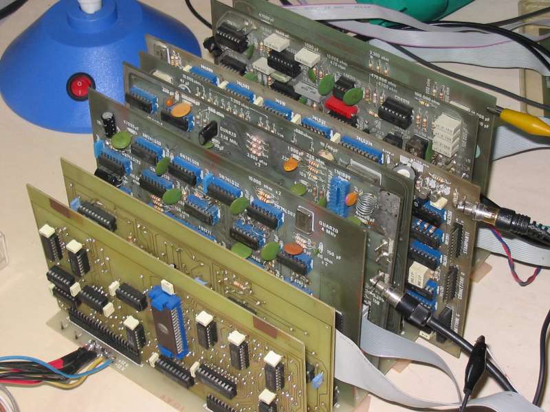
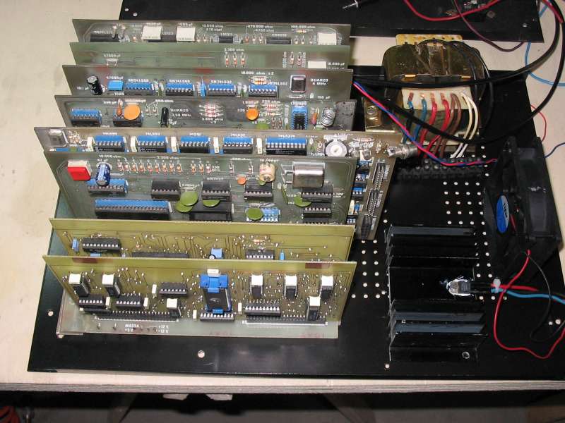
Let's try to plug cards in the bus. On front there is the eprom card made by me.
Will they work?....
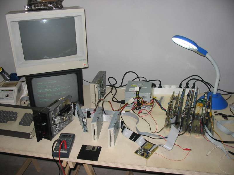
The workbench is a bit in disorder....
Here you can see 3" 1/2 floppy drives connected to their interface

The cards, the hexadecimal keyboard, and the oscilloscope.
I feel that a bit of debug is needed...
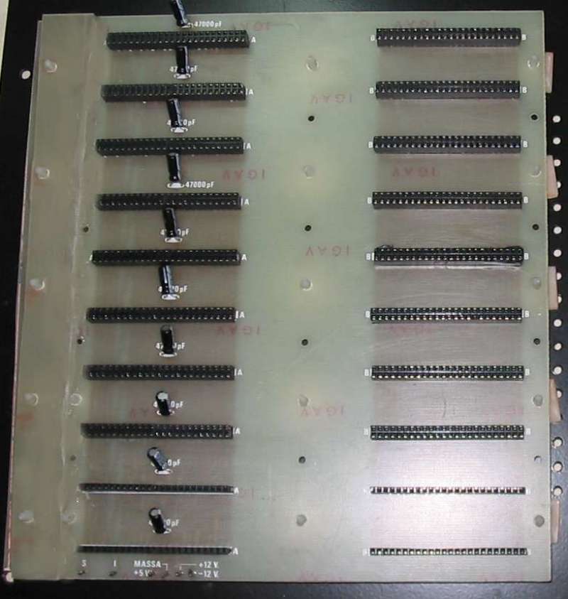
Card are normally kept in place by the bus connectors only, and everything is always a bit instable.
So I made an extension of the bus card (on the left) to mount some slices to keep cards in place
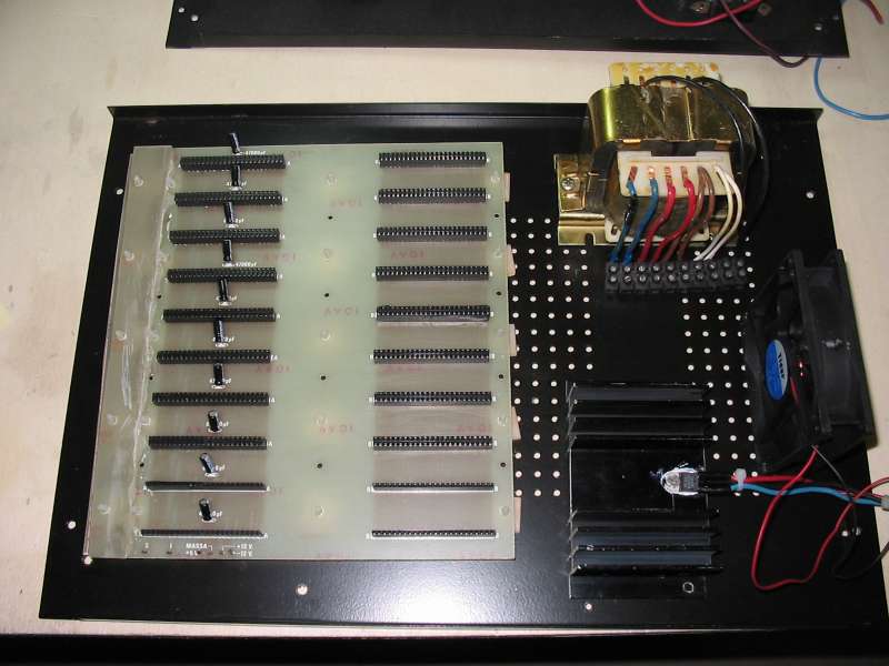
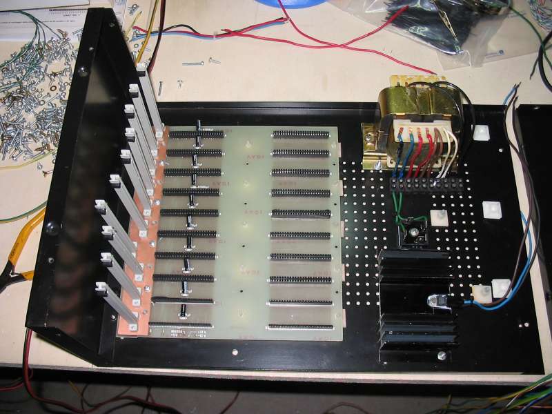
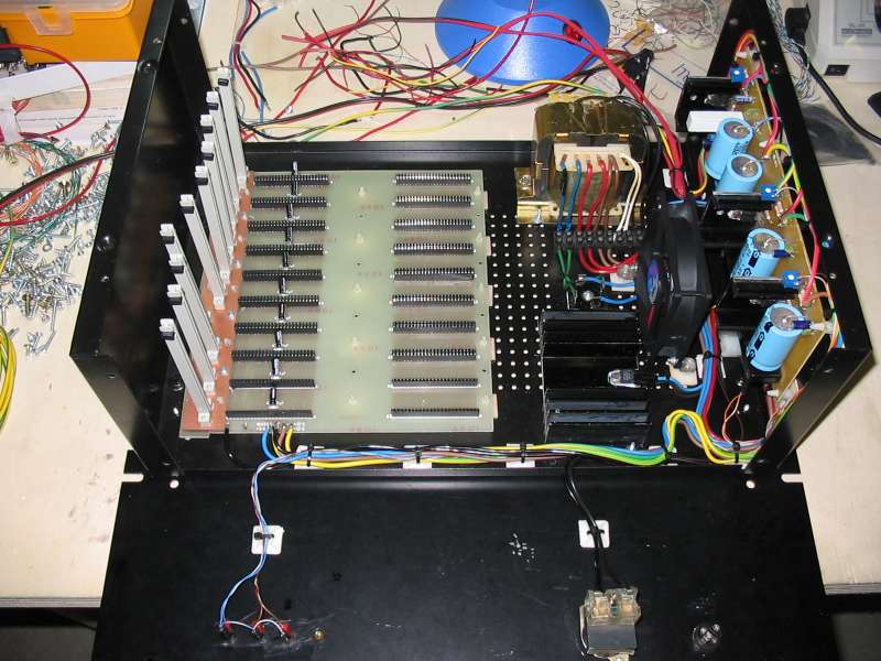
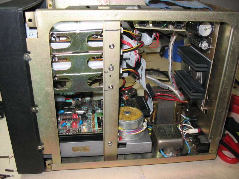
Let's try to position the bus card, transformer and cooler on the metallic case floor
And then let's try to position the power supply on the case side. With everything in place there isn't much space at disposal....
I wonder how will be all cards positioned in the case....
I would say that it could be good
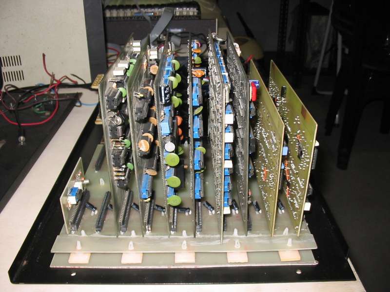
The cards seen by side
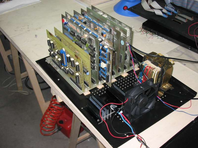
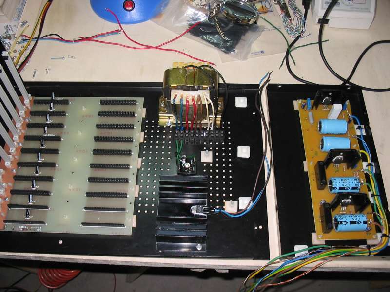
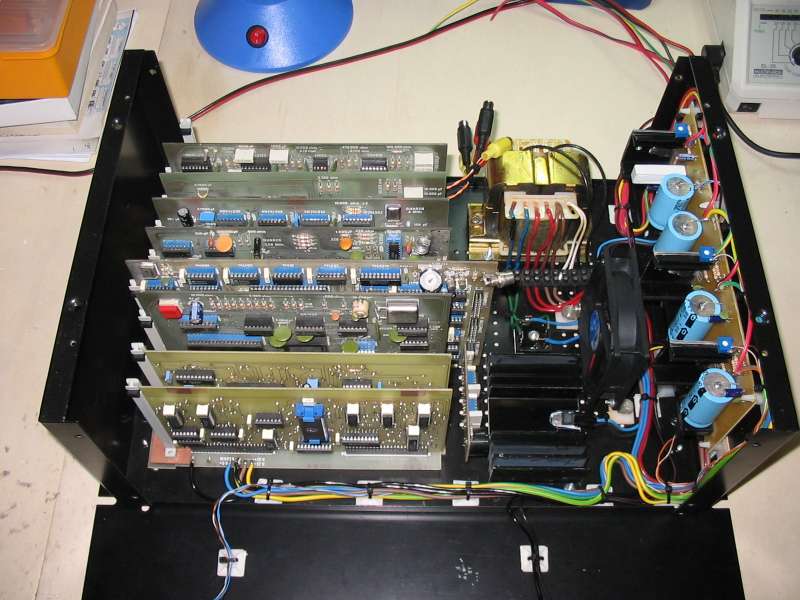
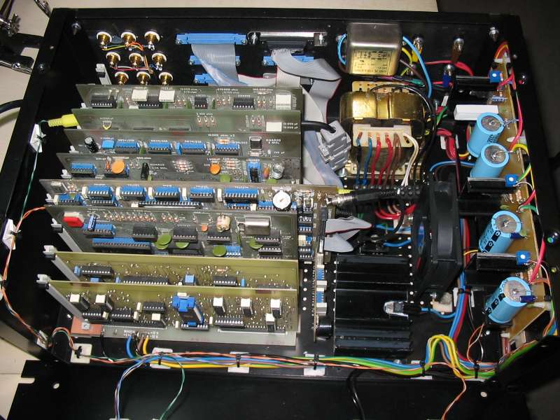
An all together view about how the final positioning will be: cards, transformer, power supply cooler and cooling fan
The vertical slices to keep cards in place mounted on the bus

The cards mounted on the bus and attached to the slices.
Now everything is alot more solid...

The building from another angle...
Let's connect a few cables to the power supply.
I suppose there will be alot of them....
Approaching the power supply
The building with the power supply from another angle

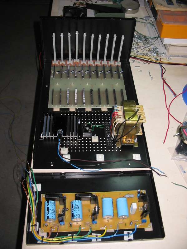
Let's raise the side with the power supply and connect all needed cables.
Yes, there are alot of them....

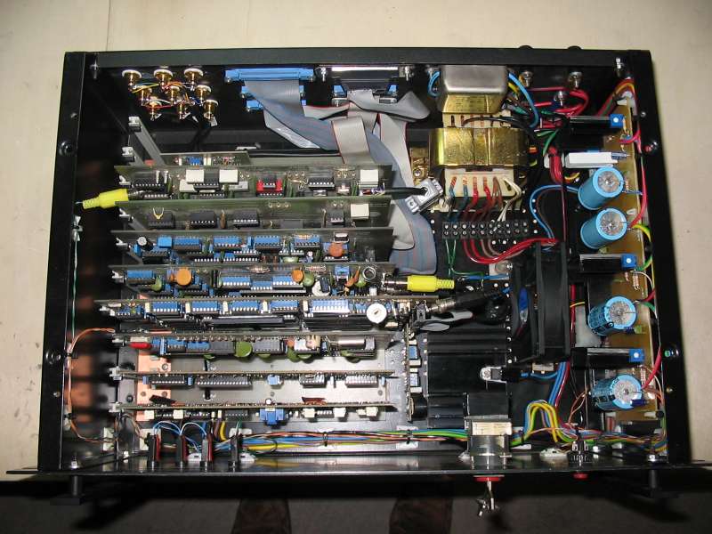
A upper view
Now it's time for the front panel: let's position cables for leds and for power key
And now let's try to put the cards on the bus.
There is still space for everything?!?
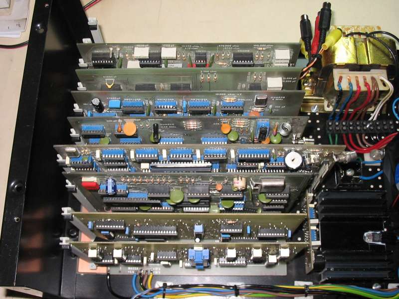
A top view of cards

Another all together view....
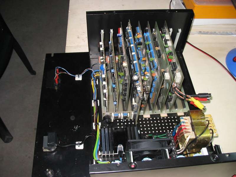
Another angle....
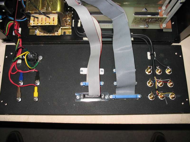
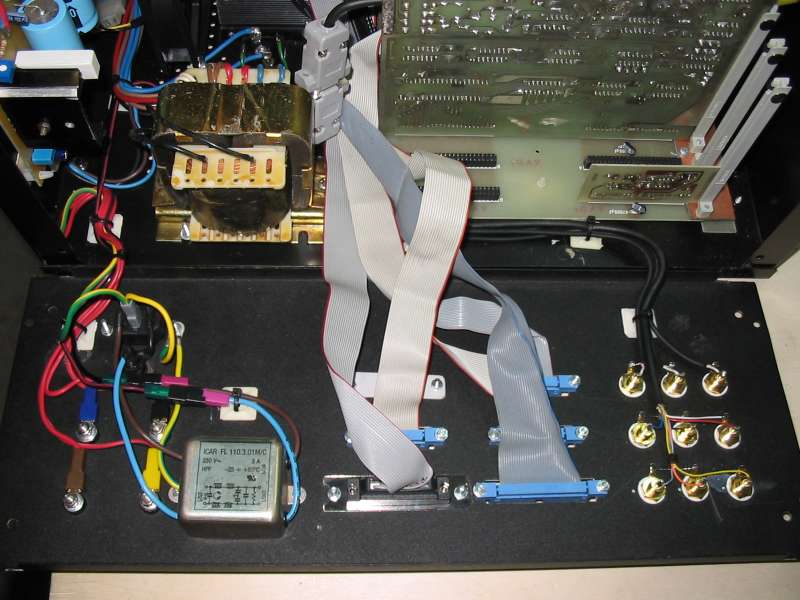
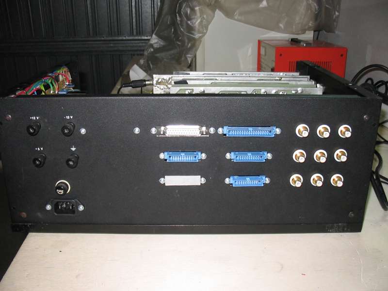
Now it's time for the rear panel.
On the left there are clips with power supply signals that are available for any external devices.
On center there are flat cables for keyboards, printer and floppy drives.
On the right there are wrist pins for video outputs and for two tapes in/out

A particular of video outputs and tapes in/out.
I like this cabling...
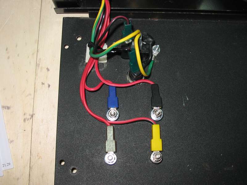
Particular of clips with power supply signals.
All three power supply signals (+5, +12, -12) and ground are available for external circuits
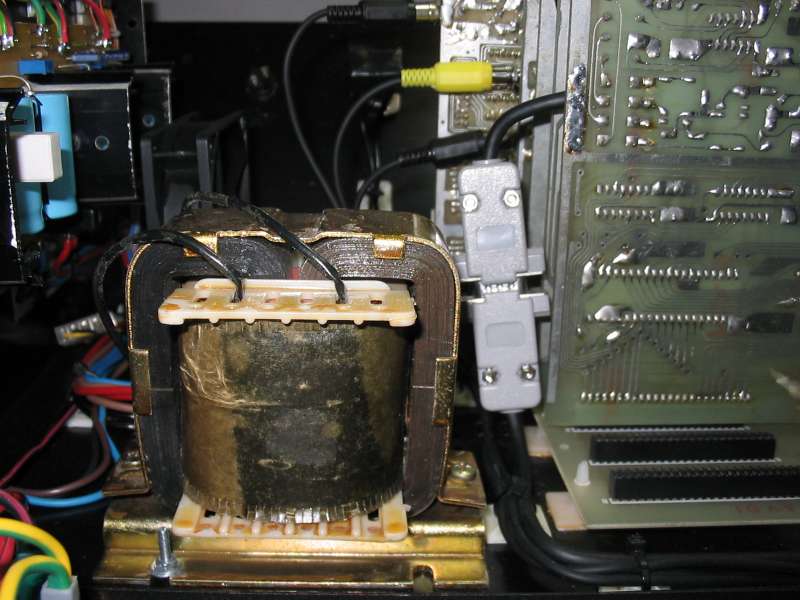
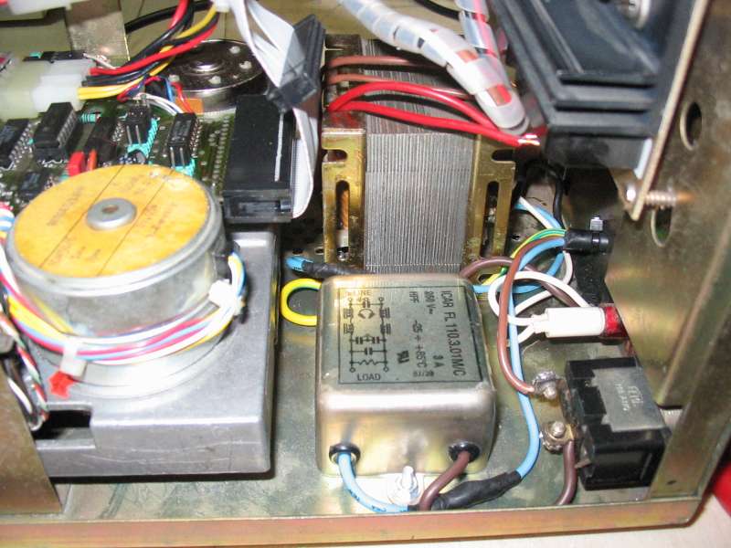
Particular of the power supply transformer.
This only transformer gives all powers needed by the computer
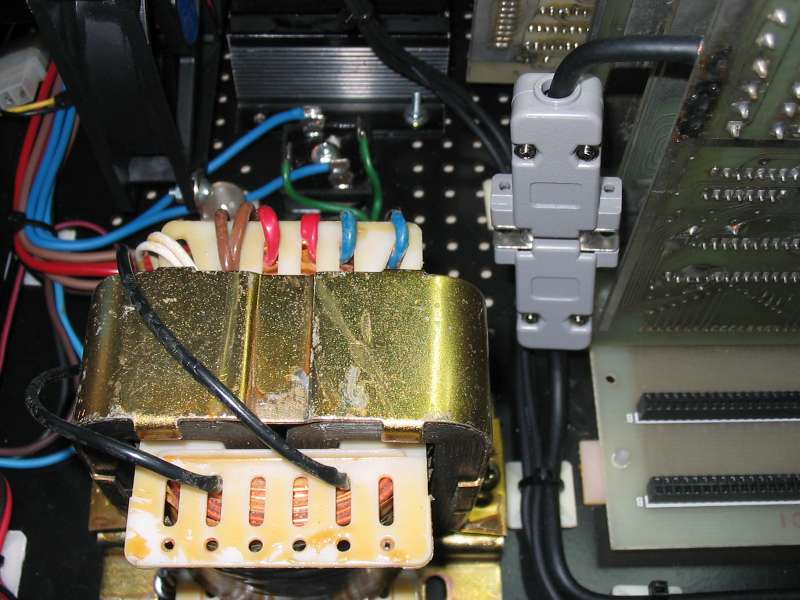
Particular of the power supply transformer.
Note the pc-standard centronics connector used to bring all connections for the tape interface to the wrist pins on the rear panel
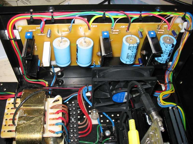
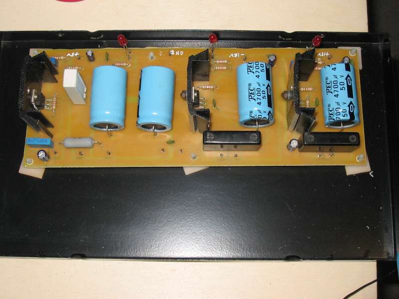
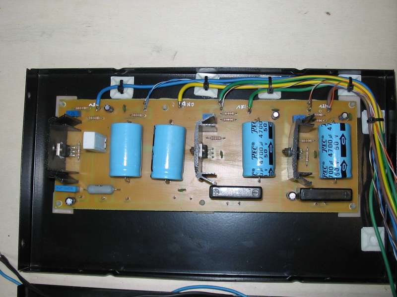
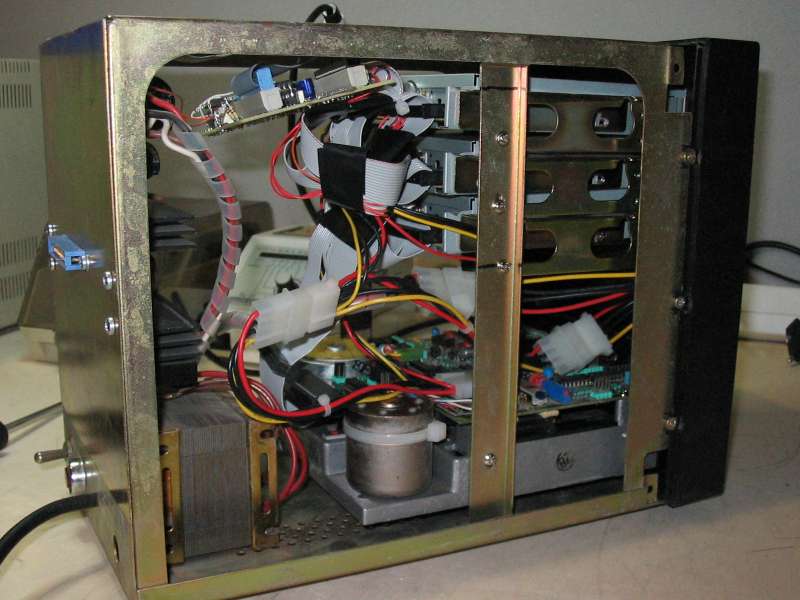
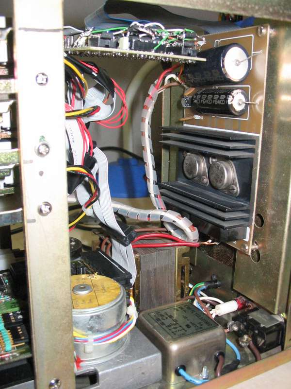
The complete power supply: transformer, cooler, bridge rectifier for 5V (on the case floor), power supply and cooler fan
The power supply seen from rear

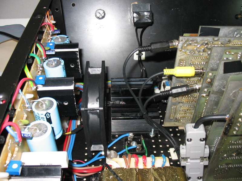
Cooler fan, transformer, cooler and cards
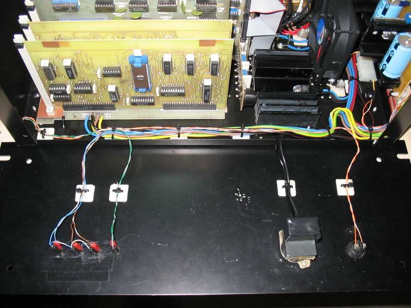
The front panel lowered with all connections made

After some tests I realize that the computer is too sensitive to external interferences, so I decide to mount a filter on the main power
The filter is positioned on the rear panel.
With the closed panel it will go exactly over the power transformer
And now let's close the rear panel.
It's really beautiful....
Everything with the closed rear panel and flat cables connected to cards.
Although the big crowding the ventilation is optimal

And this is the computer with also the front panel closed

Front panel view
And an upper view....

Again a side view of the power supply

And here a view of cards....
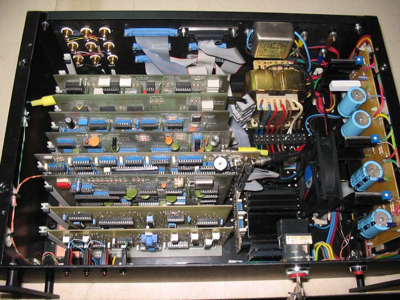
Everything from top.
Nothing bad I would say...

And now it's time for the keyboard LX.387-B...
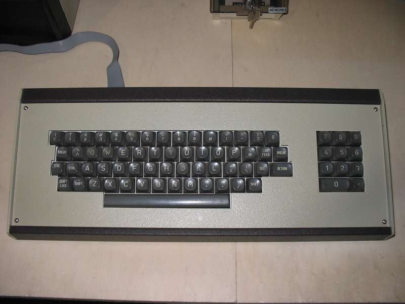
...that will be put in its metallic case
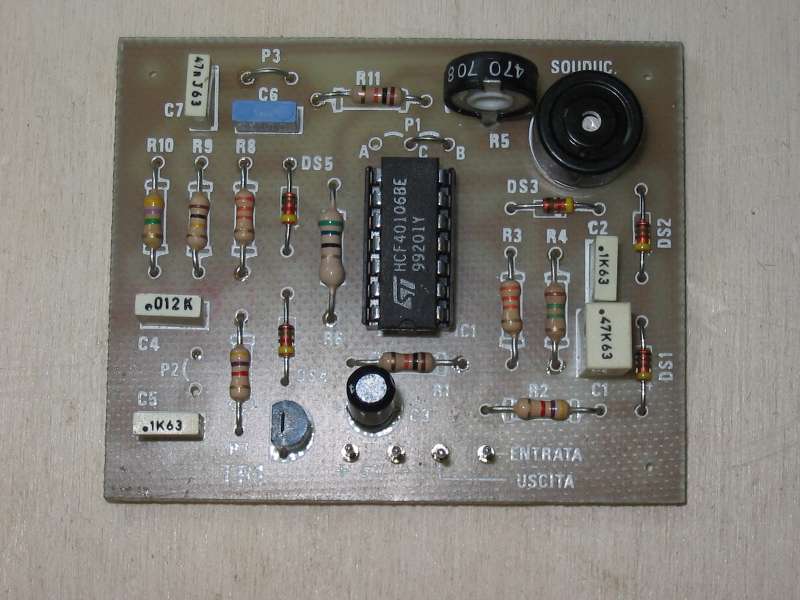
Then I build the autorepeat and keyboard beeper card, that originally I didn't own
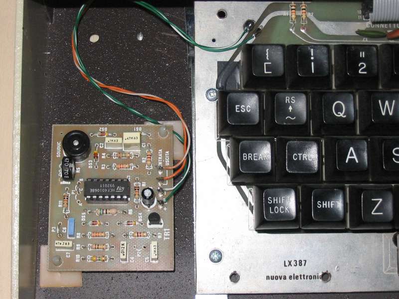
The autorepeat card is put in the LX.387 keyboard case
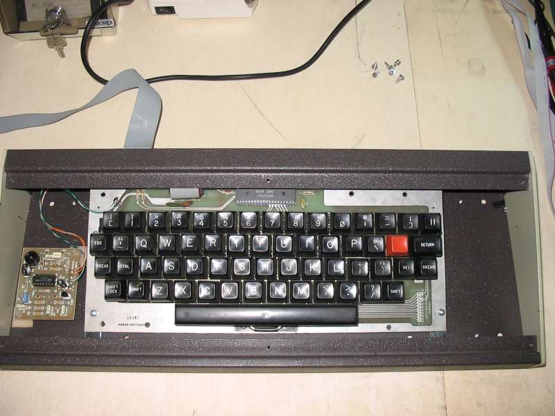
The keyboard LX.387 with the autorepeat card

The keyboard LX.387 fully assembled. Due to the fact that the case for this keyboard was not available, I used the same case of the keyboard LX.387-B and I build an ad-hoc plastic grey panel
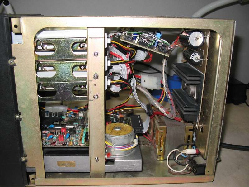
Then it's time for the floppy drives.
Here you can see the inside: three 3" 1/2 drives upper, and 5" Basf drive lower.
On the right of the photo (on the case back) there is the power supply, and on center top there is the interface made by me that lets to connect 3" 1/2 drives to the computer
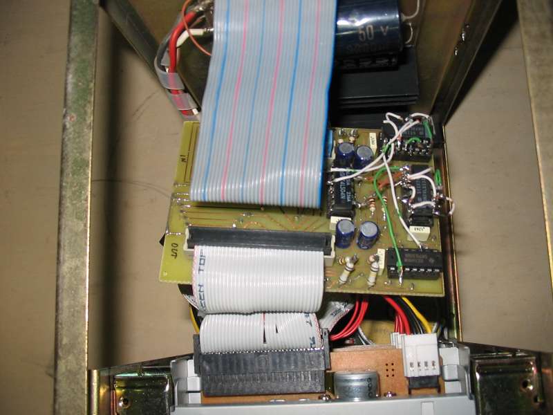
The interface that lets to connect 3" 1/2 drives seen from top.
Unfortunately, due to a design error that I saw after the printed circuit was built, I had to use "piggyback" tecnique to add some chips and make it works....
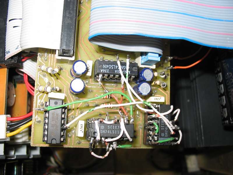
A particular of the interface that lets to connect 3" 1/2 drives
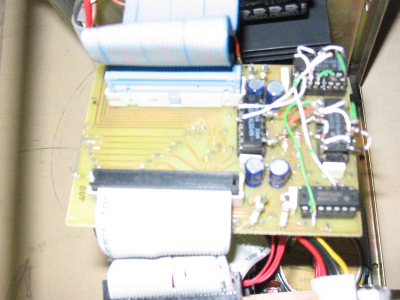
Again the interface with its two connectors
The other side of the case with drives

The rear of the drives case with the connector on the center
I mount a filter on the main power for the drives power supply also
The drives with the main power filter
The power supply on the right and the interface on top

The drives case with three 3" 1/2 drives on top, and 5" 1/4 Basf drive on bottom
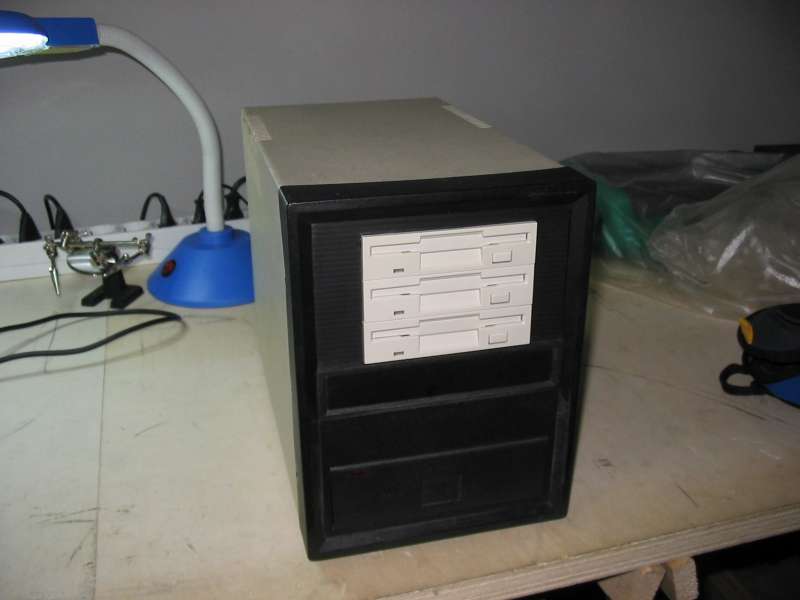
Another drives case view.
The beige case is metallic with black plastic panel

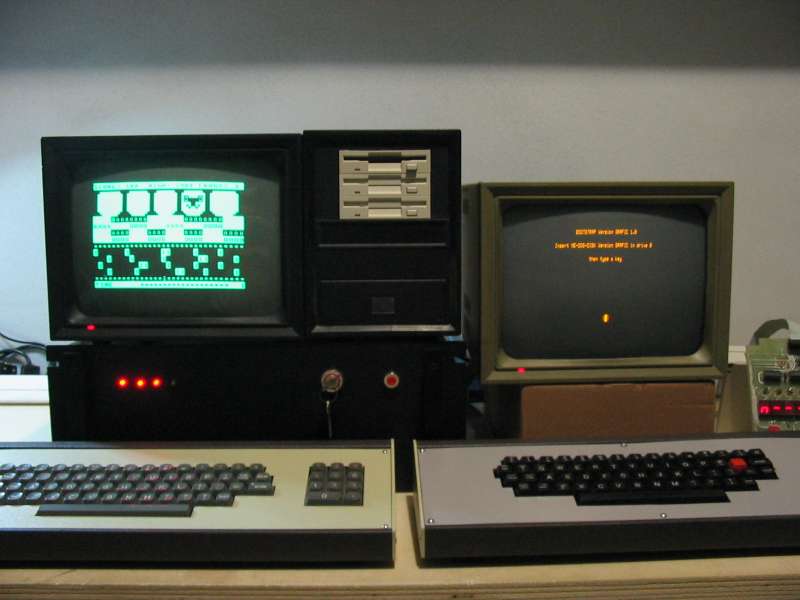
And here there is all the computer.
They aren't two, it's only one with two keyboards and two monitors.
And no, it's not a multi-user system, but there are two video cards and two keyboard interfaces... ;-)
And there is also the little hexadecimal keyboard with display (on the right)
It works !!!!!
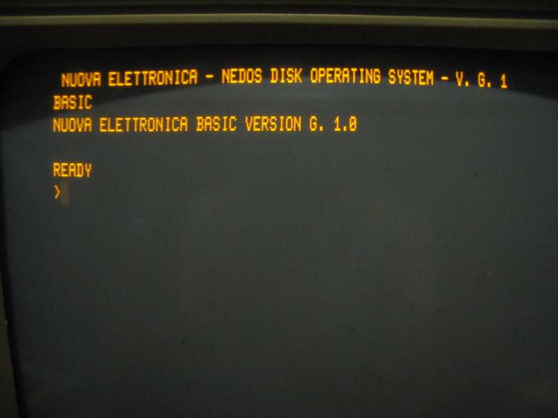
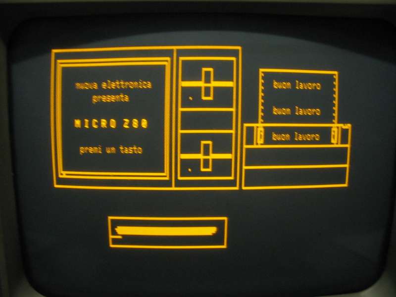
This is the boot screen of NE-DOS version G.1, used with the video graphic card LX.529
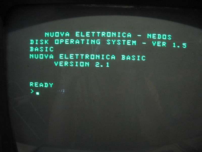
And this is the boot screen of NE-DOS version 1.5, used with video card LX.388
And now what could we do? ;-)
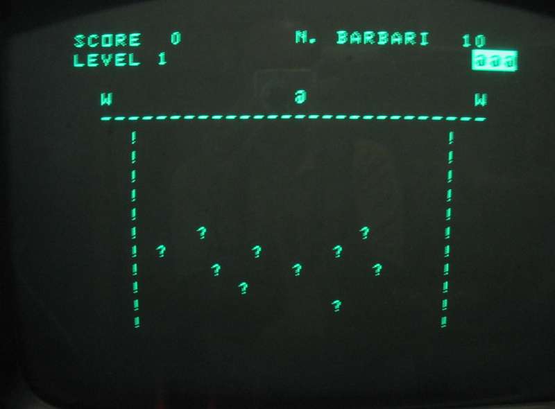
This game is named "barbarians", and I programmed it more than 30 years ago...
High resolution graphics with the graphic video card LX.529
The various monitor photos are "rounded", but it's only an optical effect due to the vicinity of the camera: in reality the lines are straights and parallels
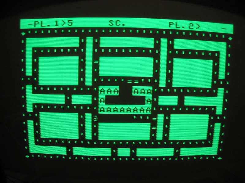
This is a PacMan clone, obviously programmed in basic...
Note the drawing particularly sophisticated.... ;-)
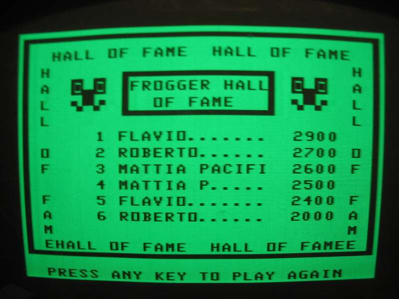
This is the initial screen of a "Frogger" clone, also programmed by me in basic 30 years ago...

Another initial screen of "Frogger"
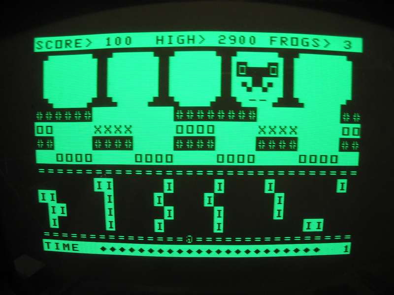
And this is "Frogger" in action.
A frog is already arrived at home... ;-)
All the computer powered up and working!!!
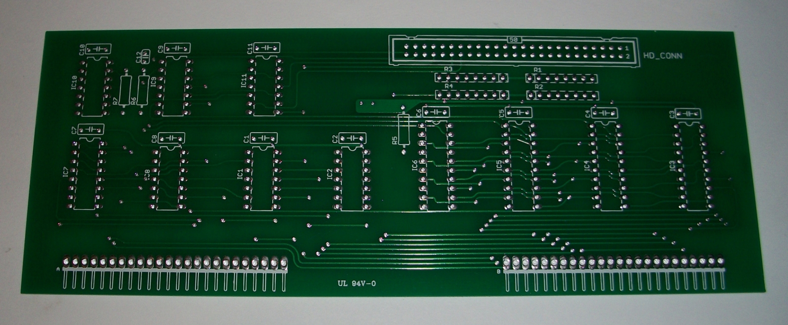
After alot of time I made the printed board for LX.683 hard-disk interface, starting from the original draws on the magazine.
Due to the fact that I don't own an original one, the printed board has beed made from scratch by redrawing all tracks using Eagle
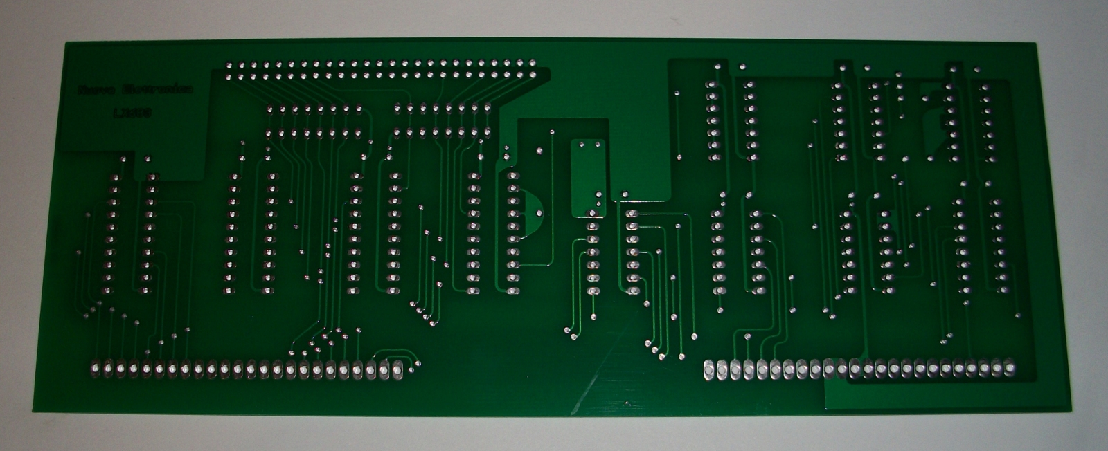
Rear of hard-disk interface LX.683 printed board

Assembled LX.683 interface

Hard-disk cable.
On the left there is 50 pin female connector for the interface, on the right there is DB-25 connector for the rear of the computer case, with all standard SCSI-I connections (that is almost identical to SASI that's used by LX.683 interface)
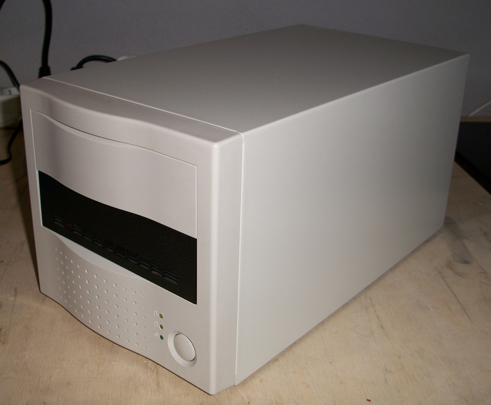
The hard-disk (a Seagate ST-225 MFM) put into a standard SCSI-I case
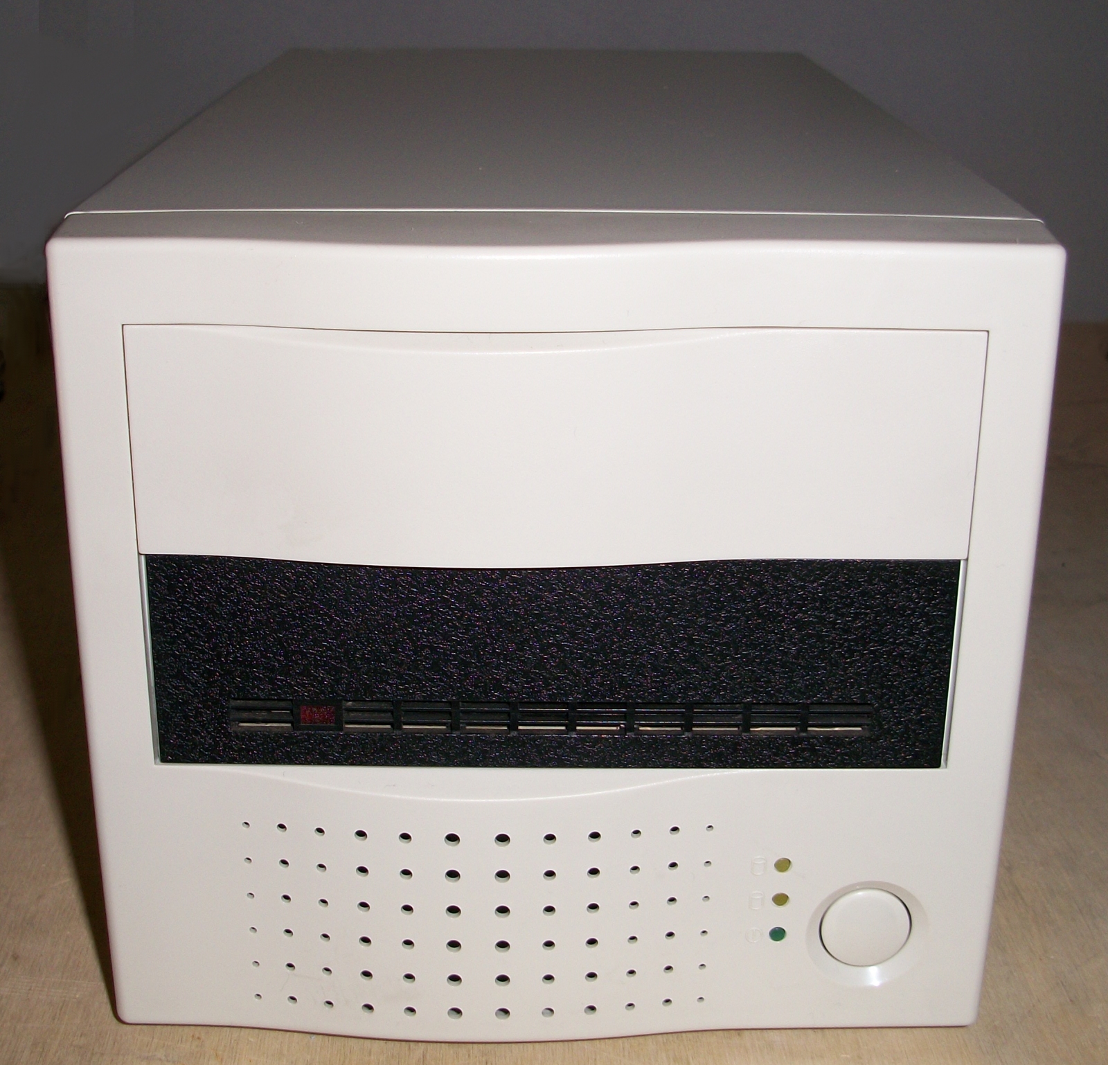
Case front with the hard-disk. This case has it's own power supply
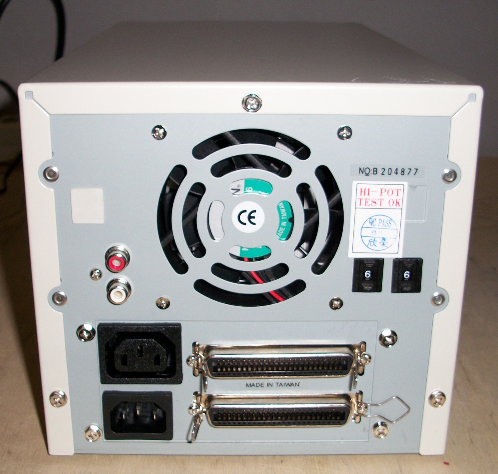
Hard-disk case rear. The connectors pinout is standard: a standard SCSI-I cable is used to connect it to the computer case
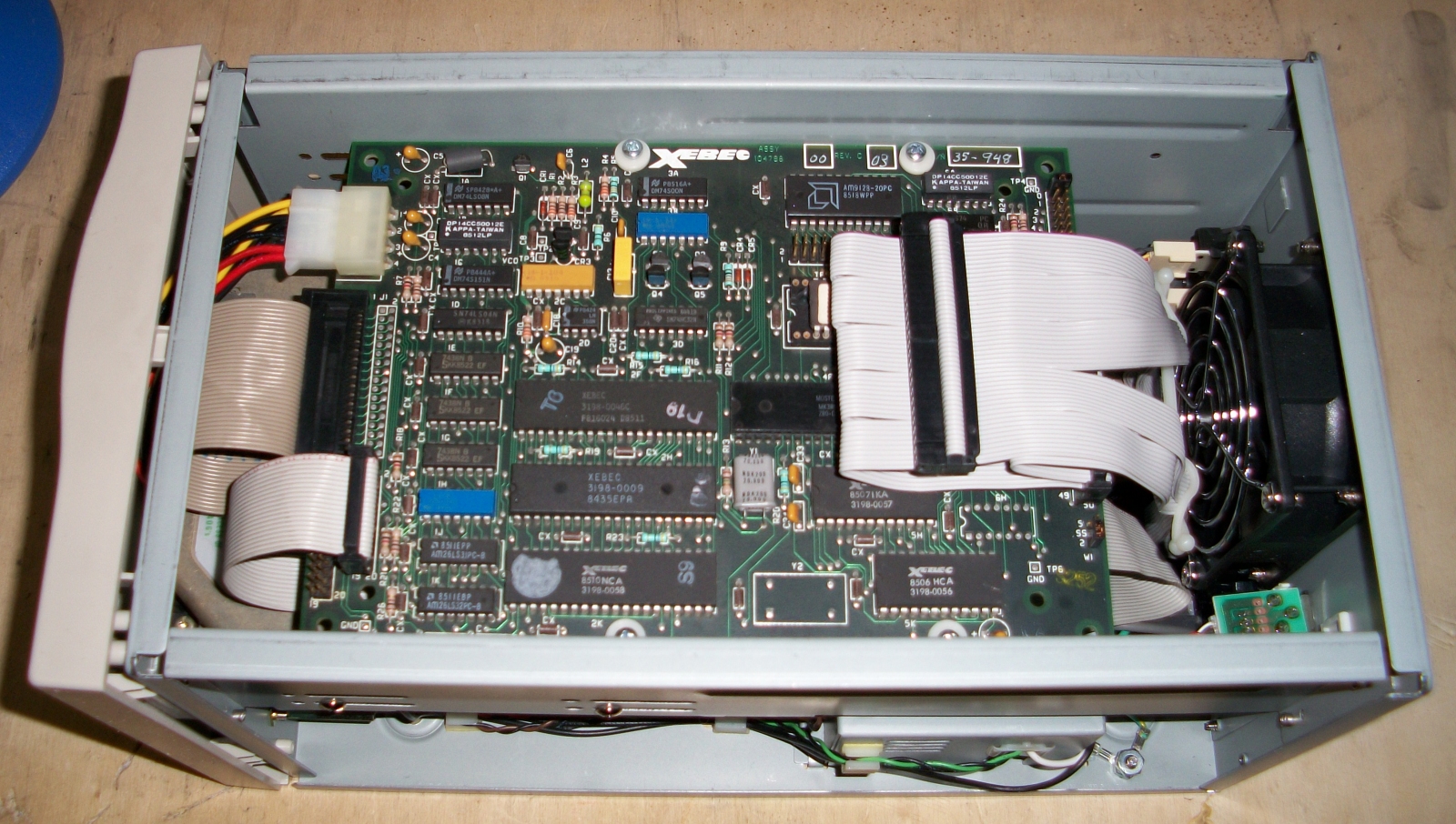
Case internal with XEBEC S-1410A controller in front view, mounted over the hard-disk
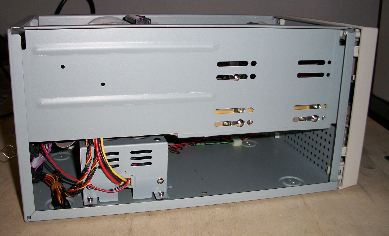
Hard-disk case internal. On the bottom there is the power supply
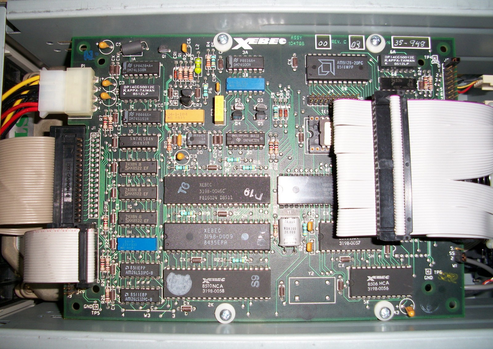
Front view of the XEBEC S-1410A controller

Hard-disk formatting
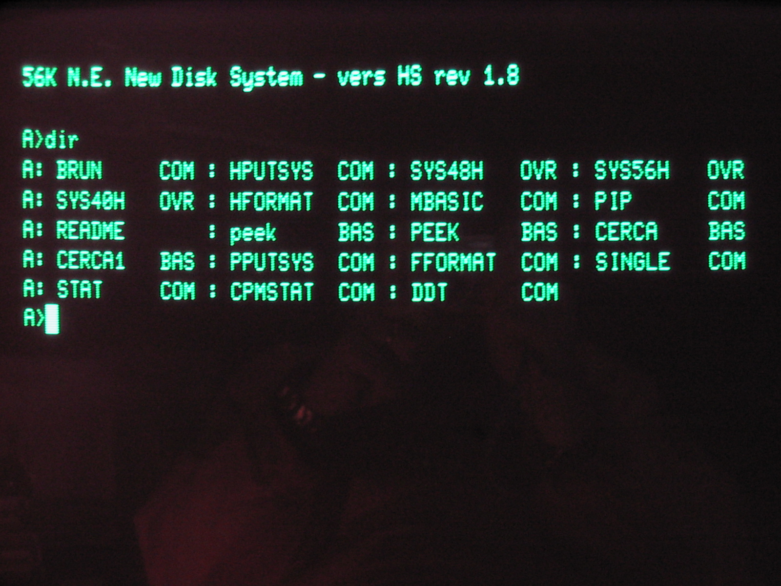
Hard-disk directory, after S.O.N.E. files have been copied to the hard-disk